Wireless ESP32 Joystick Game Controller with TFT Display | DIY Guide
Introduction
The world of DIY electronics and indie game development has been revolutionized by affordable microcontrollers like the ESP32 and vibrant graphical interfaces powered by TFT displays. In this guide, you’ll learn how to combine an ESP32 development board with a small TFT screen to create a wireless joystick game controller. Whether you’re building a custom arcade stick, a remote gamepad for your PC, or an experimental IoT-enabled gaming peripheral, this project demonstrates the core concepts needed to get started.
Why Use ESP32 and TFT Display for a Game Controller?
Built-In Wi-Fi & Bluetooth The ESP32 includes both Wi-Fi and Bluetooth Low Energy, making it easy to transmit joystick data wirelessly without additional modules.
High-Quality Graphics Modern TFT modules deliver crisp colors and fast refresh rates, perfect for displaying real-time joystick positions and game stats.
Compact and Low-Power With efficient power consumption and a small footprint, an ESP32 + TFT controller is portable and battery-friendly.
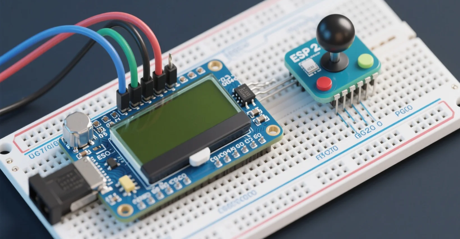
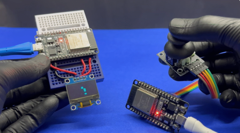
Hardware connection steps demonstration
📦 Required Components
ESP32 Development Board (e.g., DevKitC)
2.4″ or 2.8″ SPI TFT Display (ILI9341 or ST7789 driver)
// Send via Bluetooth or Wi-Fi // Example: SerialBT.printf("%d,%d,%d\n", xVal, yVal, btnPressed); delay(50); }
📡 Wireless Communication Options
Bluetooth Serial: Pair with PC or mobile for low-latency control.
ESP-NOW: Native ESP32 protocol for ultra-fast, peer-to-peer packets.
Wi-Fi UDP: Broadcast joystick data to any device on the network.
🚀 Application Scenarios
Home Arcade Cabinet Replace bulky joysticks with a wireless TFT controller for MAME or RetroPie systems.
DIY Drone Controller Display flight telemetry in real time on the TFT, while steering with the joystick.
Robot Teleoperation Control robots or IoT actuators remotely, with live sensor data shown on screen.
Interactive Art Installations Map joystick input to visuals or sound, creating engaging experiences.
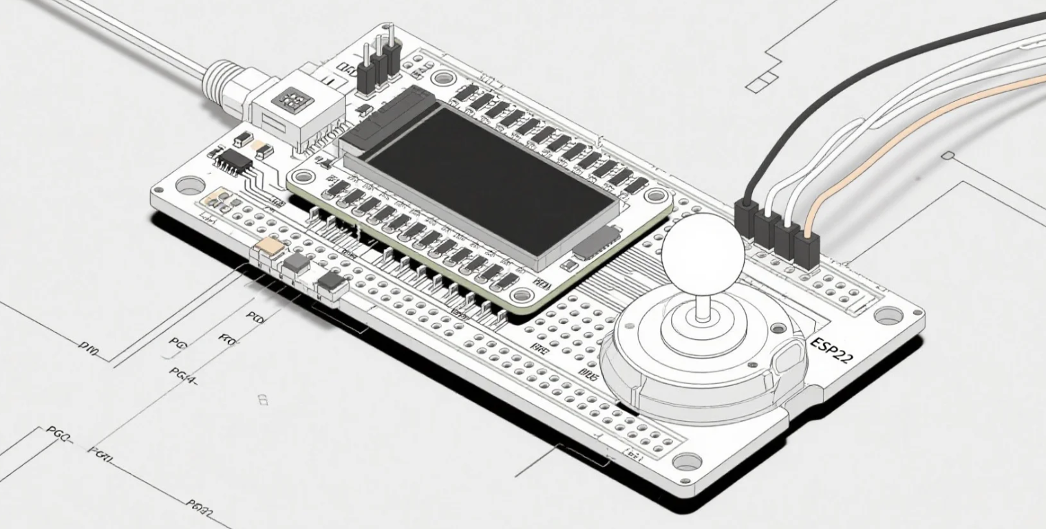
Building a Wireless Joystick Game Controller with ESP32 and TFT Display
💡 Tips for Optimization
Debounce the Button: Implement software debounce for reliable presses.
Screen Refresh: Only redraw moving elements to minimize flicker.
Power Saving: Put ESP32 into light sleep between updates for battery life.
Error Handling: Detect communication loss and display status on TFT.
Conclusion
Combining an ESP32 microcontroller with a vibrant TFT display and an analog joystick opens up endless possibilities for gaming peripherals and interactive IoT devices. With built-in wireless, high-contrast graphics, and flexible customization, this project showcases how modern embedded components can elevate DIY controllers to professional levels.
Call to Action
Ready to build your own wireless joystick controller? Share your questions or project photos in the comments below!